

 English
 Español
 Deutsch
Precision Gears And Shafts form the core of many mechanical transmission systems. Gears transfer rotational motion and torque, while shafts support the rotating components and transmit power between c...
READ MORE
About

Zhejiang Haoshun Machinery Technology Co., Ltd.
Zhejiang Haoshun Machinery Technology Co., Ltd. is located in Taizhou Bay Industrial Park, Jiaojiang District, Taizhou City, Zhejiang Province. Spanning a total area of more than 56,000 square meters and featuring a substantial building area of 70,000 square meters, the company is a technology-based enterprise specializing in the production of precision gears, shafts, gear sleeves, gear rings, and a variety of other essential components. These products serve a broad spectrum of industries, including automotive, agricultural machinery, construction machinery, and reducer applications.
At the core of the company's strength lies its advanced production and testing equipment, which together form a comprehensive closed-loop production system. Every stage of manufacturing, from blank forging to rough machining, precision machining, and heat treatment, is conducted in-house, ensuring rigorous quality control and high-efficiency output. This vertically integrated approach allows the company to maintain superior product consistency and accelerate delivery times while meeting the evolving demands of clients.
Supporting this robust manufacturing infrastructure is a highly skilled team of 360 employees, including 15 senior and intermediate technical personnel and 25 professionals dedicated to quality management and inspection. Their collective expertise continuously refines the company's product design and manufacturing capabilities, ensuring that every component is produced with exceptional precision and performance reliability.
Haoshun Machinery's product portfolio finds extensive application across multiple sectors. By supplying critical drivetrain components to the automotive, agricultural machinery, construction machinery, and reducer industries, the company has developed the flexibility to offer customized gear products and integrated solutions tailored to the specific needs of diverse clients.
Financially, the company has demonstrated robust growth with annual sales revenue reaching 450 million RMB. This success is underpinned by a lean and agile operational team that has forged enduring partnerships with major OEMs and industry-leading clients, further solidifying the company's reputation as a reliable and strategic partner.
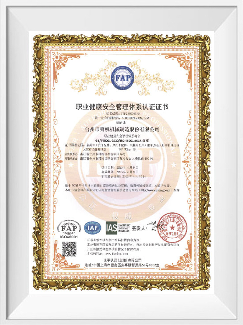
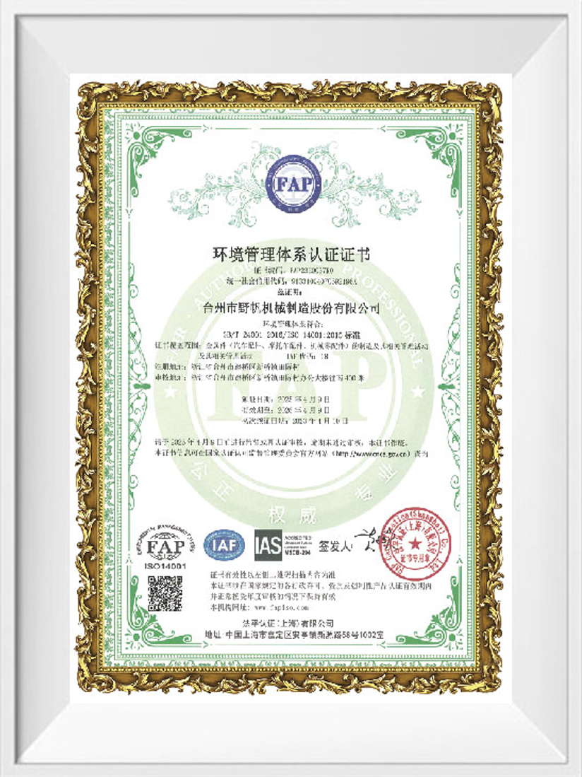
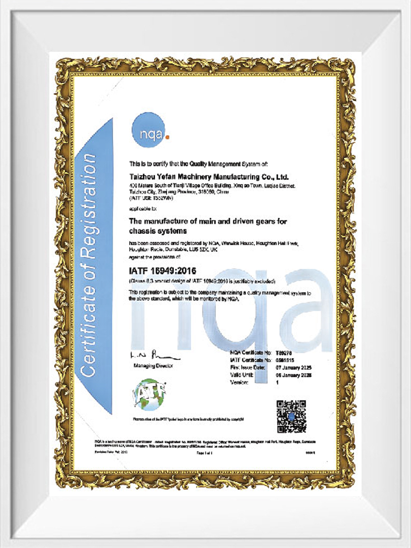
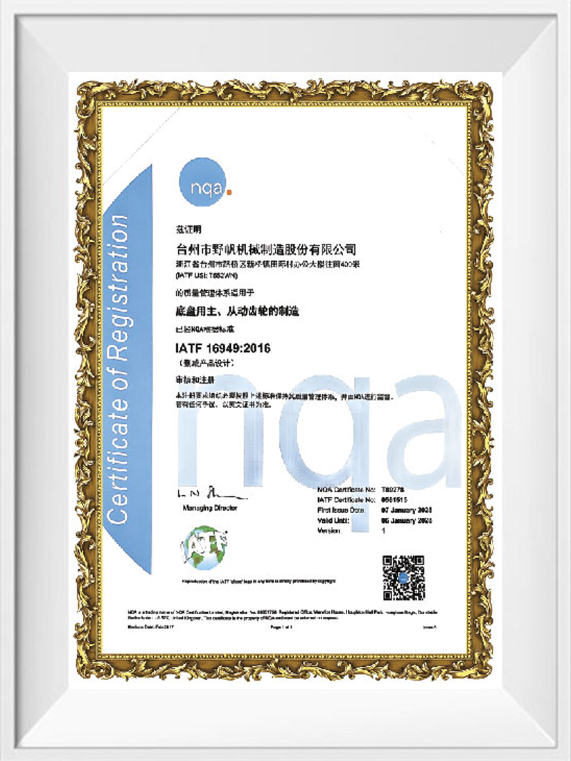
Quality assurance remains a cornerstone of Haoshun Machinery's operations. Since achieving IATF 16949 certification in 2013, the company has embedded a comprehensive quality management system across all levels of its workforce, ensuring that every product leaving the facility conforms to stringent international standards. This commitment to excellence has earned the company multiple accolades, including recognition as a Top 100 Chinese Quality Credit Enterprise, an AAA-level Credit Enterprise, and an Outstanding Enterprise.
Looking ahead, Zhejiang Haoshun Machinery Technology Co., Ltd. remains steadfast in its guiding philosophy of “Innovation-driven, Quality First.” The company is committed to advancing its research and development capabilities, expanding its presence in both domestic and international markets, and striving to become a globally recognized leader in gear and transmission system solutions. Through continuous innovation and an unwavering focus on customer satisfaction, Haoshun aims to deliver not only high-quality, high-precision E-Drive Reducer & EV Transmission Gears but also comprehensive technical support and tailored solutions to clients around the world.
Certificate Of Honor
News
-
-
Inside a transmission system, the final transfer of rotational force depends on several components working together. An Output Gear Shaft is one of the parts that carries this process toward the drive...
READ MORE -
The demand for compact mechanical transmission systems is placing greater attention on how individual gear components contribute to overall equipment layout. A Hollow Worm Gear offers an interesting s...
READ MORE -
Gear conversations typically center on transmitting rotational power from one shaft to another, but a surprising number of mechanical systems need the opposite: turning rotation into straight-line mov...
READ MORE -
An internal combustion engine masks gear whine that would be immediately obvious in an electric vehicle, since there is no engine noise left to cover it once the motor becomes the loudest thing under ...
READ MORE -
A gear that meets every dimension on an inspection report can still get rejected during a supplier qualification audit if the paperwork behind it cannot answer a simple question: which batch of raw ma...
READ MORE -
A gear that meets every dimension on a drawing can still fail an OEM's supplier audit if the paperwork behind it doesn't hold up. Electric drivetrain gear manufacturing for automotive and Tier-supplie...
READ MORE -
Specification decisions around a crawler gear in a truck system rarely come from a single department within a fleet operation, since the requirement usually surfaces from whoever directly experiences ...
READ MORE -
Bore tolerance rarely gets discussed outside engineering drawings, yet it determines whether a hollow output shaft performs reliably in service or introduces vibration and premature wear that shows up...
READ MORE -
Heavy vehicle engineers rarely talk about top speed when they discuss a crawler gear in truck applications, because the entire point of this gear range is the opposite: moving forward at walking pace ...
READ MORE -
Torque transmission looks straightforward from a distance, but the moment a design engineer needs to route a cable, shaft, or pipe through the center of a rotating assembly, a hollow output shaft beco...
READ MORE -
Transmission Gears in industrial systems are rarely evaluated only at the installation stage. In many production lines and mechanical assemblies, what matters more is how gear behavior changes once co...
READ MORE
Industry knowledge
The power output characteristics of electric vehicles differ fundamentally from those of traditional internal combustion engines. Electric motors are capable of delivering high torque across a wide range of rotational speeds and exhibit extremely rapid transient response times; this inherent characteristic endows electric drive systems with unique advantages regarding their requirements for reduction gears. Reduction gears are not merely simple speed-conversion devices; rather, they serve as a critical bridge linking the specific characteristics of the electric motor with the dynamic performance requirements of the vehicle. Consequently, the soundness of their design directly impacts the vehicle's overall dynamic performance and energy efficiency.
Mechanical Principles of Gear Meshing and Efficiency Optimization
A comprehensive understanding of the transmission principles governing electric drive reduction gears necessitates a return to the fundamental mechanical mechanisms of gear meshing. When a pair of gears engages, the normal force acting at the point of contact between the tooth surfaces can be resolved into a tangential force and a radial force; the tangential force drives the rotation of the driven gear, while the radial force acts upon the bearing system. The stress distribution within the tooth-surface contact zone adheres to Hertzian contact theory; the big contact stress occurs in the vicinity of the pitch line, and its magnitude is closely correlated with the normal load, the radius of curvature of the tooth surfaces, and the material's elastic modulus.
Energy losses during the gear meshing process primarily stem from the following sources:
- Sliding Friction Loss: Power dissipation resulting from relative sliding between tooth surfaces; the sliding velocity is maximal at the points of gear entry and exit, and drops to zero at the pitch line.
- Rolling Friction Loss: Hysteresis losses generated by the rolling contact between tooth surfaces, which are intrinsically linked to the damping characteristics of the material.
- Oil Churning Loss: Fluid resistance generated by the rotation of the gears agitating the lubricating oil; this loss is closely dependent on the oil's viscosity, the depth of gear immersion in the oil, and the rotational speed.
- Windage Loss: Aerodynamic resistance resulting from the interaction between the high-speed rotating gears and the surrounding air.
Based on the aforementioned principles, the optimization of efficiency in electric drive reduction gears can be approached from multiple dimensions. At the level of tooth profile design, increasing the contact ratio—the average number of tooth pairs simultaneously in mesh—enables multiple tooth pairs to share the load concurrently, thereby reducing the contact stress on individual teeth and small the sliding distance per unit of tooth width. Helical gear designs further enhance the overall contact ratio by introducing an axial contact ratio; moreover, the meshing process in helical gears is smoother, resulting in good noise characteristics compared to spur gears. Regarding material selection, the use of materials characterized by a moderate elastic modulus and relatively high internal damping properties contributes effectively to the reduction of rolling friction losses. At the level of lubrication design, precisely controlling fluid viscosity and oil supply volume—thereby small churning losses while ensuring adequate lubrication—constitutes a crucial strategy for optimizing efficiency.
Principles of Planetary Gear Reduction and Structural Advantages
Planetary gear reduction represents a significant technological branch within the field of electric drive reduction gearing; its transmission principle differs fundamentally from that of fixed-axis gear transmission. A planetary gear mechanism consists of four basic components: the sun gear, the planetary gears, the planetary carrier, and the ring gear. The planetary gears simultaneously rotate about their own axes and revolve around the axis of the sun gear, carried by the planetary carrier; this compound motion endows planetary transmissions with unique mechanical characteristics.
The core principle of planetary gear reduction lies in power splitting. After the input power is transmitted through the sun gear, it is simultaneously shared and transmitted by multiple planetary gears to the planetary carrier or the ring gear for output. Assuming there are n planetary gears, then under ideal conditions, each planetary gear bears only 1/n of the total load. This allows the planetary gear mechanism to achieve a more compact structure and lighter weight for a given load-bearing capacity. For electric drive systems, this characteristic is particularly valuable, as the lightweighting of the reducer directly contributes to enhancing the vehicle's overall power density and driving range.
The calculation of the transmission ratio in planetary gear reduction adheres to the principles governing the speed relationships within planetary gear trains. Taking a typical configuration—featuring a sun gear input, a planetary carrier output, and a fixed ring gear—as an example, the transmission ratio is calculated as i = 1 + Z_ring / Z_sun, where Z_ring represents the number of teeth on the ring gear and Z_sun represents the number of teeth on the sun gear. By varying the selection of the fixed component as well as the input and output components, a single planetary gear mechanism can achieve multiple transmission ratios; this inherent flexibility facilitates the modular design of electric drive systems. Planetary reduction schemes used in electric drive applications typically incorporate the following technical features:
- Multi-stage Planetary Cascading: By cascading two or three stages of planetary gear sets, extremely high transmission ratios—exceeding 30:1—are achieved within a remarkably compact axial envelope.
- Compound Planetary Structure: This design organically integrates differential gear sets with fixed-axis gear sets to achieve a synergistic optimization of power splitting and speed synthesis.
- Flexible Planetary Carrier: The use of thin-walled or split-type planetary carrier designs improves load distribution uniformity and relaxes the precision requirements for manufacturing and assembly.
- Load-Equalizing Mechanism: Load balancing among individual planetary gears is achieved through the use of floating components or elastic elements, thereby enhancing overall system reliability.
Performance Parameter Comparison of Different Technical Approaches
The selection of a technical approach for electric drive reduction gearing requires a comprehensive assessment of multiple factors, including transmission efficiency, load-bearing capacity, structural dimensions, and manufacturing costs. The table below provides a systematic comparison of key performance indicators for current mainstream technical solutions:
| Technical Solution | Typical Transmission Ratio Range | Single-Stage Efficiency | Structural Compactness | Load-Bearing Capacity | Manufacturing Cost | Primary Vehicle Applications |
| Single-Stage Fixed-Axis | 7-12 | 97%–98.5% | Moderate | Moderate | Low | Compact Passenger Cars, Small SUVs |
| Two-Stage Fixed-Axis | 12-25 | 95%–97% | Average | High | Moderate | Mid-size Passenger Cars, Light Commercial Trucks |
| Single-Stage Planetary | 3-12 | 96%–98% | Good | High | High | High-Performance Passenger Cars, Electric Drive Axles |
| Two-Stage Planetary | 15-50 | 94%–96% | Good | Very High | High | Heavy Commercial Vehicles, Specialty Vehicles |
| Compound Planetary | 10-30 | 95%–97% | Good | Very High | Very High | Premium Passenger Models, Sports Cars |
Although planetary reduction schemes may not hold an advantage in terms of manufacturing costs, their exceptional structural compactness and load-bearing capacity render them indispensable in scenarios where space is constrained or load requirements are particularly demanding. Conversely, the two-stage fixed-axis reduction scheme strikes a good balance between transmission ratio range and load-bearing capacity, making it a common configuration for electric drive systems in commercial vehicles.
information to be updated
Submit feedback
Let’s Build Your Perfect product.
-
William Weber:
Phone: +86-13968651722
E-mail: sales01@hsgearworks.com -
Flora:
Phone: +86-13738533719
E-mail: sales05@hsgearworks.com -
Address:
No.9 East Section, Jianan Avenue, Taizhou Bay New District, Taizhou City, Zhejiang Province, China, 318052
Copyright @ Zhejiang Haoshun Machinery Technology Co., Ltd. All Rights Reserved.
EV Transmission Gears Supplier
