
 English
 Español
 Deutsch


Specification decisions around a crawler gear in a truck system rarely come from a single department within a fleet operation, since the requirement usually surfaces from whoever directly experiences ...
READ MOREStabilizer/Outrigger Drive Gears
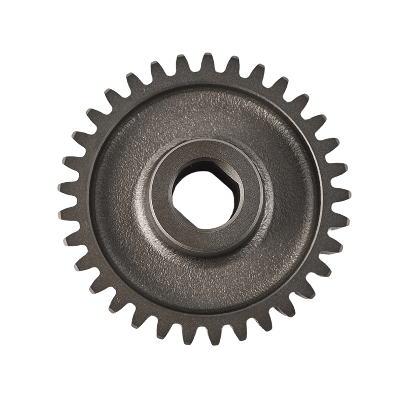
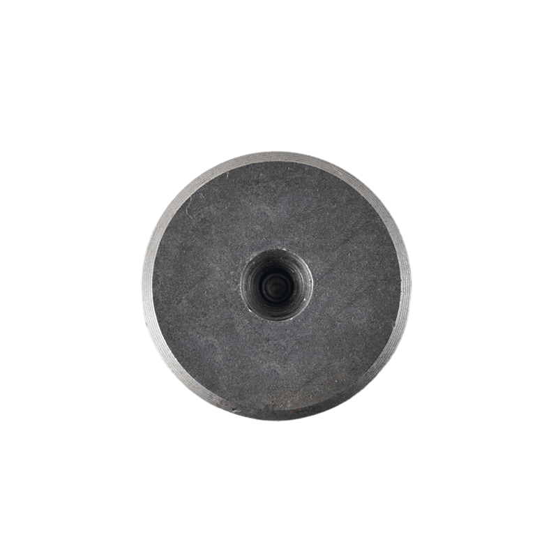
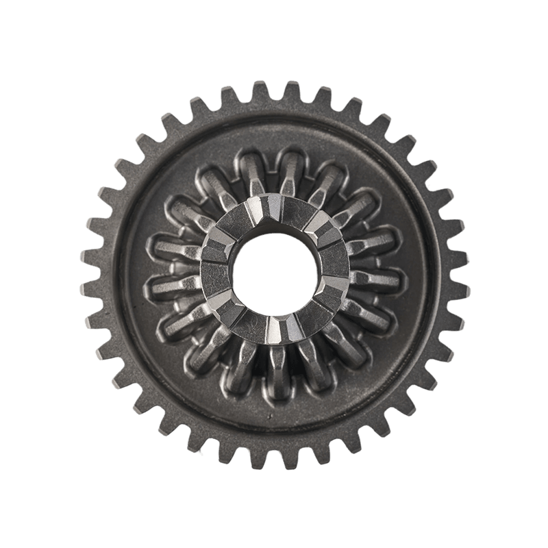
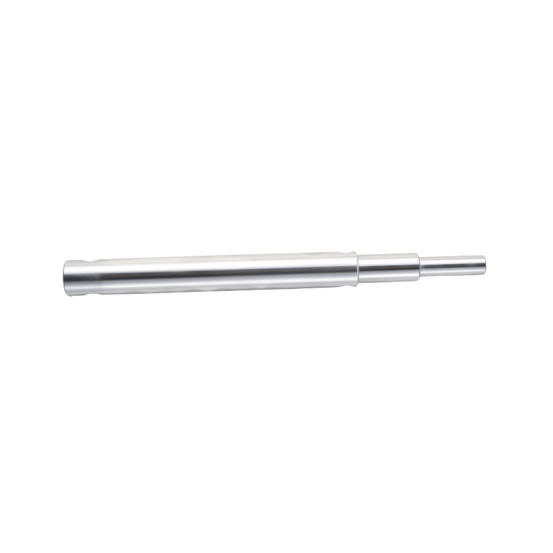
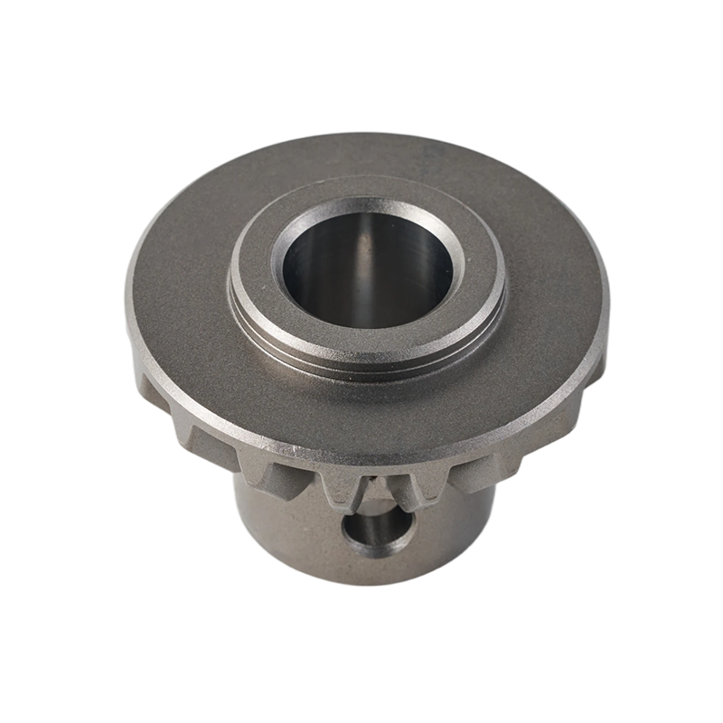
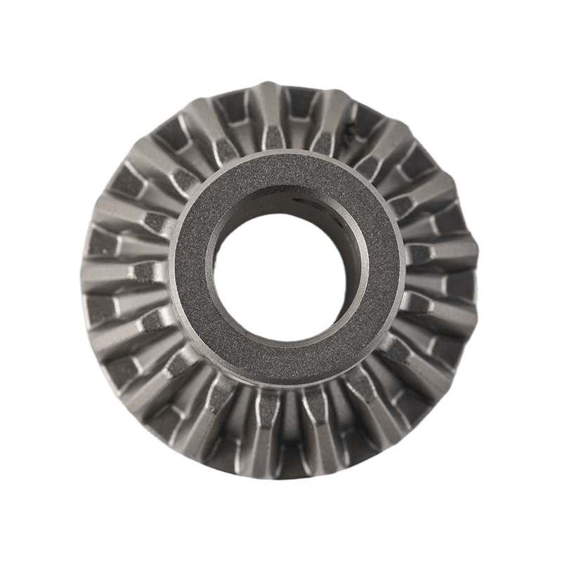
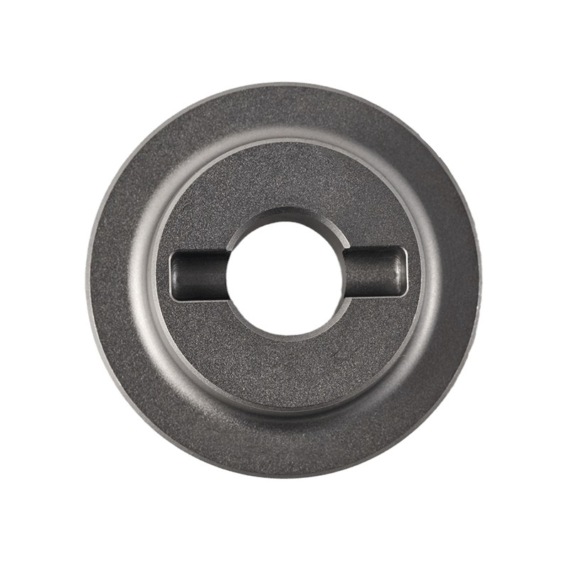
Stabilizer/Outrigger Drive Gears is used in crane stabilizers and outrigger drive systems, where torque, wear life and repeatable fit matter. Key priorities are load holding, durability, and field reliability for repeatable parts in series production. Common deliverables include drive gears, gear shafts, and drive components. At Haoshun Gearworks, the focus is repeatability: stable processes, clear checkpoints, and consistent output.
Consistent tooth contact starts with stable blanks and controlled heat treatment, then finishes with precision machining and structured inspection. Depending on the design, we use forged blanks or bar stock, then apply controlled heat treatment to balance hardness and toughness. Machining focuses on interface accuracy, and tooth finishing is selected to match your noise and life targets. We verify critical dimensions and interface fits so your assembly line sees predictable parts, batch after batch.
From drawing confirmation to samples and volume orders, we provide responsive engineering communication and export packaging support. Typical documents include EN 10204 3.1 material certificates, inspection reports, and quality warranty letters. Choose this category when you need a gear supplier that can scale, keep quality steady, and support approvals with proper documents. For repeat orders, we keep process parameters stable to reduce variation and shorten re-approval cycles.
About

Zhejiang Haoshun Machinery Technology Co., Ltd.
Zhejiang Haoshun Machinery Technology Co., Ltd. is located in Taizhou Bay Industrial Park, Jiaojiang District, Taizhou City, Zhejiang Province. Spanning a total area of more than 56,000 square meters and featuring a substantial building area of 70,000 square meters, the company is a technology-based enterprise specializing in the production of precision gears, shafts, gear sleeves, gear rings, and a variety of other essential components. These products serve a broad spectrum of industries, including automotive, agricultural machinery, construction machinery, and reducer applications.
At the core of the company's strength lies its advanced production and testing equipment, which together form a comprehensive closed-loop production system. Every stage of manufacturing, from blank forging to rough machining, precision machining, and heat treatment, is conducted in-house, ensuring rigorous quality control and high-efficiency output. This vertically integrated approach allows the company to maintain superior product consistency and accelerate delivery times while meeting the evolving demands of clients.
Supporting this robust manufacturing infrastructure is a highly skilled team of 360 employees, including 15 senior and intermediate technical personnel and 25 professionals dedicated to quality management and inspection. Their collective expertise continuously refines the company's product design and manufacturing capabilities, ensuring that every component is produced with exceptional precision and performance reliability.
Haoshun Machinery's product portfolio finds extensive application across multiple sectors. By supplying critical drivetrain components to the automotive, agricultural machinery, construction machinery, and reducer industries, the company has developed the flexibility to offer customized gear products and integrated solutions tailored to the specific needs of diverse clients.
Financially, the company has demonstrated robust growth with annual sales revenue reaching 450 million RMB. This success is underpinned by a lean and agile operational team that has forged enduring partnerships with major OEMs and industry-leading clients, further solidifying the company's reputation as a reliable and strategic partner.
Quality assurance remains a cornerstone of Haoshun Machinery's operations. Since achieving IATF 16949 certification in 2013, the company has embedded a comprehensive quality management system across all levels of its workforce, ensuring that every product leaving the facility conforms to stringent international standards. This commitment to excellence has earned the company multiple accolades, including recognition as a Top 100 Chinese Quality Credit Enterprise, an AAA-level Credit Enterprise, and an Outstanding Enterprise.
Looking ahead, Zhejiang Haoshun Machinery Technology Co., Ltd. remains steadfast in its guiding philosophy of “Innovation-driven, Quality First.” The company is committed to advancing its research and development capabilities, expanding its presence in both domestic and international markets, and striving to become a globally recognized leader in gear and transmission system solutions. Through continuous innovation and an unwavering focus on customer satisfaction, Haoshun aims to deliver not only high-quality, high-precision Stabilizer/Outrigger Drive Gears but also comprehensive technical support and tailored solutions to clients around the world.
Certificate Of Honor
News
-
-
Bore tolerance rarely gets discussed outside engineering drawings, yet it determines whether a hollow output shaft performs reliably in service or introduces vibration and premature wear that shows up...
READ MORE -
Heavy vehicle engineers rarely talk about top speed when they discuss a crawler gear in truck applications, because the entire point of this gear range is the opposite: moving forward at walking pace ...
READ MORE -
Torque transmission looks straightforward from a distance, but the moment a design engineer needs to route a cable, shaft, or pipe through the center of a rotating assembly, a hollow output shaft beco...
READ MORE -
Transmission Gears in industrial systems are rarely evaluated only at the installation stage. In many production lines and mechanical assemblies, what matters more is how gear behavior changes once co...
READ MORE -
A companion flange is rarely the component that brings a machine into the workshop. Technicians are usually called because of vibration, leakage, unusual drivetrain behavior, or wear discovered elsewh...
READ MORE -
An experienced mechanic once described a gearbox inspection in a way that surprised a younger technician. Before opening the housing, he simply stood beside the vehicle and listened. Not for a loud fa...
READ MORE -
A transmission gear shaft rarely attracts much attention during daily operation. When a gearbox is running smoothly, technicians are usually focused on noise levels, temperature readings, lubrication ...
READ MORE -
Inside many transmission systems, noise rarely appears suddenly. Operators may only hear a light rhythmic sound during acceleration or notice slight vibration at certain rotational speeds. Weeks later...
READ MORE -
In heavy industrial machinery systems, gear assemblies play a pivotal role in power transmission and torque distribution. Given that their operating environments typically involve high loads and prolo...
READ MORE -
In the powertrain systems of commercial electric vehicles, the reduction gearbox serves as a critical link in power transmission. Its primary function is to modify the high-speed, low-torque output ge...
READ MORE -
Industrial power transmission systems play a vital role in the energy conversion and transfer processes within various types of mechanical equipment. Among their core components, gears hold fundamenta...
READ MORE
Industry knowledge
The outrigger stabilizer drive gear assembly serves as a critical transmission component within this system; its primary function is to transmit power to the outrigger extension mechanism, thereby facilitating operations such as outrigger extension, retraction, and positional adjustment.
Since outrigger systems frequently operate in high-load environments, the gear assembly must not only possess the capability for stable power output but also maintain good structural integrity and operational smoothness.
Structural Composition of the Drive Gear Assembly
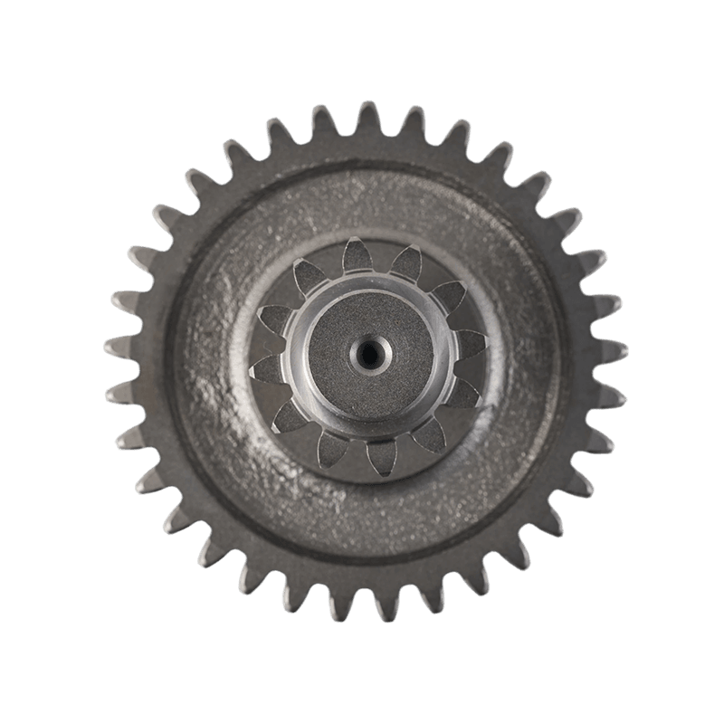
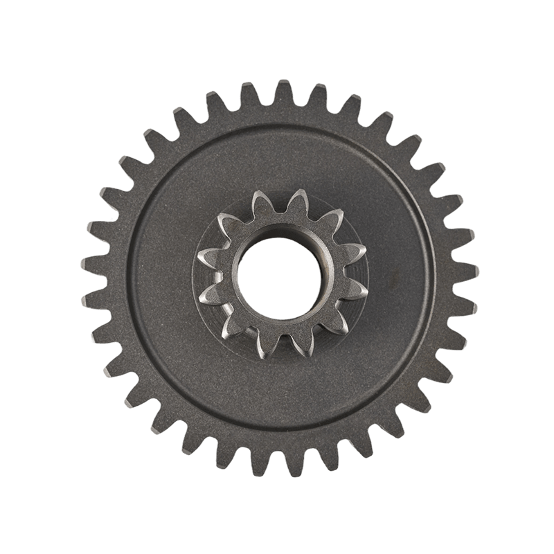
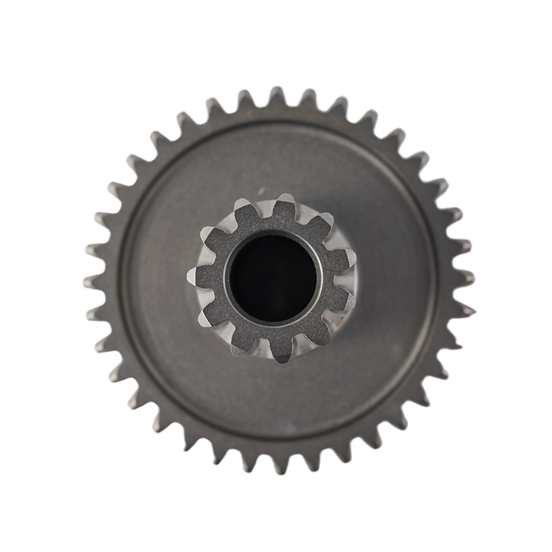
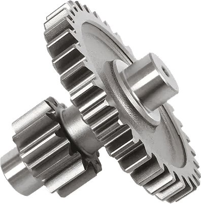
The outrigger stabilizer drive gear assembly typically consists of an input shaft, reduction gears, an output gear, a coupling mechanism, and an external housing.
The input end is responsible for receiving power output from a hydraulic motor or electric motor; the intermediate reduction mechanism utilizes multi-stage gear meshing to reduce rotational speed while simultaneously increasing output torque; finally, the output gear drives the screw or outrigger actuator to execute movement.
The entire assembly is typically housed within a sealed gearbox to small the impact of external dust, moisture, and contaminants on the gear meshing surfaces.
Common Gear Types and Application Characteristics
Outrigger stabilization systems employ a variety of gear types, with different structural configurations suited to specific load requirements and spatial constraints.
| Gear Type | Structural Characteristics | Primary Function | Common Application Location |
| Spur Gear | Simple structure; easy to manufacture | Basic power transmission | Low-speed transmission stages |
| Helical Gear | Smooth meshing; low noise levels | Continuous, stable output | Main reduction mechanism |
| Worm Gear | High reduction ratio capability | Enhanced self-locking performance | Outrigger locking system |
| Planetary Gear | Compact structure | Multi-stage reduction and torque distribution | High-load drive units |
Different gear forms are frequently combined to meet the specific power requirements of the outrigger system during various operational stages.
Characteristics of Reduction Structures in Outrigger Drives
During the extension and load-bearing phases, outriggers require substantial thrust and a stable movement velocity; consequently, the drive system typically incorporates a reduction mechanism.
The reduction gear train converts the high rotational speed at the input end into a lower-speed output while simultaneously amplifying torque, thereby enabling the outrigger to make smooth contact with the ground.
In certain heavy-duty equipment applications, multi-stage reduction systems are employed to mitigate the impact of instantaneous loads on the gear meshing surfaces. Furthermore, the speed reduction mechanism enhances the precision of the outrigger's motion control, thereby ensuring greater stability of the equipment during the leveling process.
Material Selection and Heat Treatment Processes
The drive gears within the outrigger stabilizer are subjected to significant pressure and alternating loads over extended periods; consequently, material properties play a critical role in the overall stability of the system.
Common materials for gears include medium-carbon alloy steels and carburized steels, which undergo heat treatment processes to enhance both the surface hardness of the gear teeth and the core toughness of the material.
Upon completion of gear machining, the components typically undergo quenching, tempering, and surface strengthening treatments to improve their wear resistance.
In certain high-load applications, the gear teeth also undergo precision grinding to enhance meshing accuracy and small operational vibration.
Power Transmission During Outrigger Movement
During operation, the outrigger drive gear assembly executes a multi-stage process involving power input, speed reduction and transmission, and final actuation output.
Once the power source is activated, the input shaft drives the primary gear; the rotational speed is then progressively reduced through a series of intermediate gears, transmitting the resulting torque to the output end.
The output gear subsequently drives a screw, chain, or rack-and-pinion mechanism, thereby enabling the outrigger to extend or retract.
Self-Locking Mechanisms in Outrigger Stabilizers
To prevent the outriggers from retracting inadvertently after the equipment has ceased operation, certain drive systems incorporate a self-locking mechanism.
A common form of this mechanism is the worm gear drive, characterized by its ability—under specific conditions—to prevent reverse rotation, thereby enhancing the stability of the outrigger support.
Additionally, some systems integrate mechanical locking devices or braking mechanisms to further reinforce the outrigger's fixed position while the equipment is stationary.
This design ensures that the outrigger's position remains stable even when the equipment is shut down or when external loads fluctuate.
Lubrication Systems and Sealing Design
Outrigger drive gear assemblies typically operate under high-load conditions and in outdoor environments; therefore, the design of the lubrication and sealing systems is of paramount importance to the operational integrity of the system.
Lubricating oil forms a protective film on the gear surfaces, thereby small friction and wear while simultaneously dissipating a portion of the heat generated during operation.
Common lubrication methods include splash lubrication and oil bath lubrication; for certain large-scale equipment, a circulating lubrication system may also be employed. To prevent the ingress of sediment, moisture, and dust into the gearbox, a multi-layer sealing structure—typically comprising components such as oil seals, dust rings, and gaskets—is installed externally.
Analysis of Wear Patterns During Operation
During prolonged operation, the drive gears within the outrigger stabilizer mechanism may exhibit various forms of wear.
Common occurrences include tooth surface wear, pitting, and fatigue cracking. These issues are typically correlated with load fluctuations, lubrication conditions, and manufacturing precision.
Under operating conditions involving frequent starts and stops, the gear surfaces are susceptible to impact loads, which can localized stress concentrations.
Furthermore, severe contamination of the lubricating oil can accelerate tooth surface wear and compromise meshing precision.
Consequently, periodic inspection of both the lubrication status and the condition of the gear surfaces is of critical importance for maintaining the stable operation of the system.
Submit feedback
Let’s Build Your Perfect product.
-
William Weber:
Phone: +86-13968651722
E-mail: sales01@hsgearworks.com -
Flora:
Phone: +86-13738533719
E-mail: sales05@hsgearworks.com -
Address:
No.9 East Section, Jianan Avenue, Taizhou Bay New District, Taizhou City, Zhejiang Province, China, 318052
Copyright @ Zhejiang Haoshun Machinery Technology Co., Ltd. All Rights Reserved.
Outrigger Drive Gears For Sale
