

 English
 Español
 Deutsch

Output Gear Shaft Turns Gear Rotation Into Usable Mechanical Power
Where Engineering Excellence Meets Reliable Transmission
Inside a transmission system, the final transfer of rotational force depends on several components working together. An Output Gear Shaft is one of the parts that carries this process toward the driven mechanism, combining shaft geometry with gear engagement to deliver mechanical power from the transmission to its next stage.
Although its structure may appear straightforward, the output shaft has to accommodate torque, rotational movement, bearing support, and connection requirements at the same time. Its design is therefore closely connected with the rest of the transmission assembly.
The Shaft Forms the Final Power Path
A gear transmission normally changes speed and torque before power reaches the output side. The output shaft receives this rotational movement and transfers it to the component connected to the transmission.
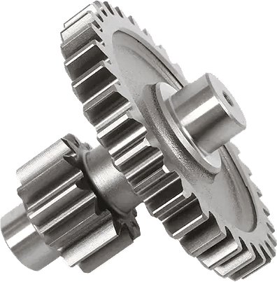
In an Output Gear Shaft, the gear and shaft are either manufactured as an integrated component or assembled according to the specific transmission design. The position of the gear teeth determines how the shaft interacts with the preceding gear stage, while the shaft section provides the connection to bearings, couplings, or other driven components.
This combination allows one component to perform both transmission and mechanical connection functions.
Gear Geometry Influences Power Transfer
The gear portion of the shaft needs to match the corresponding gear in the transmission. Tooth count, module, pressure angle, tooth profile, and gear width can all be determined by the requirements of the complete gear set.
Different transmission systems use different gear arrangements. Spur gears may be suitable for relatively straightforward power transmission, while helical gears can provide smoother engagement in applications where continuous rotation is required.
For an Output Gear Shaft, these details cannot be considered separately from the mating gear. The two components need to form a compatible working pair within the intended transmission ratio and load conditions.
Shaft Geometry Supports Mechanical Connections
The shaft section normally contains several functional areas rather than having one uniform diameter. Bearing seats, shoulders, splines, keyways, threaded sections, and other interfaces may be incorporated according to the application.
Each section serves a different purpose. Bearing surfaces support rotation, while splined or keyed areas can transfer torque to another component. Shoulders can provide positioning references within the gearbox assembly.
This makes dimensional control particularly important during machining. The shaft has to maintain the intended relationship between its different functional surfaces so that the completed assembly can operate as designed.
Material And Heat Treatment Work Together
Gear shafts operating under repeated loads require a material suitable for the mechanical conditions of the application. Alloy steel is commonly used for transmission components because its properties can be modified through heat treatment.
The gear teeth may require a harder surface to resist wear, while the shaft core needs an appropriate balance of strength and toughness. Depending on the design, processes such as carburizing, quenching, tempering, or other surface treatments can be incorporated into production.
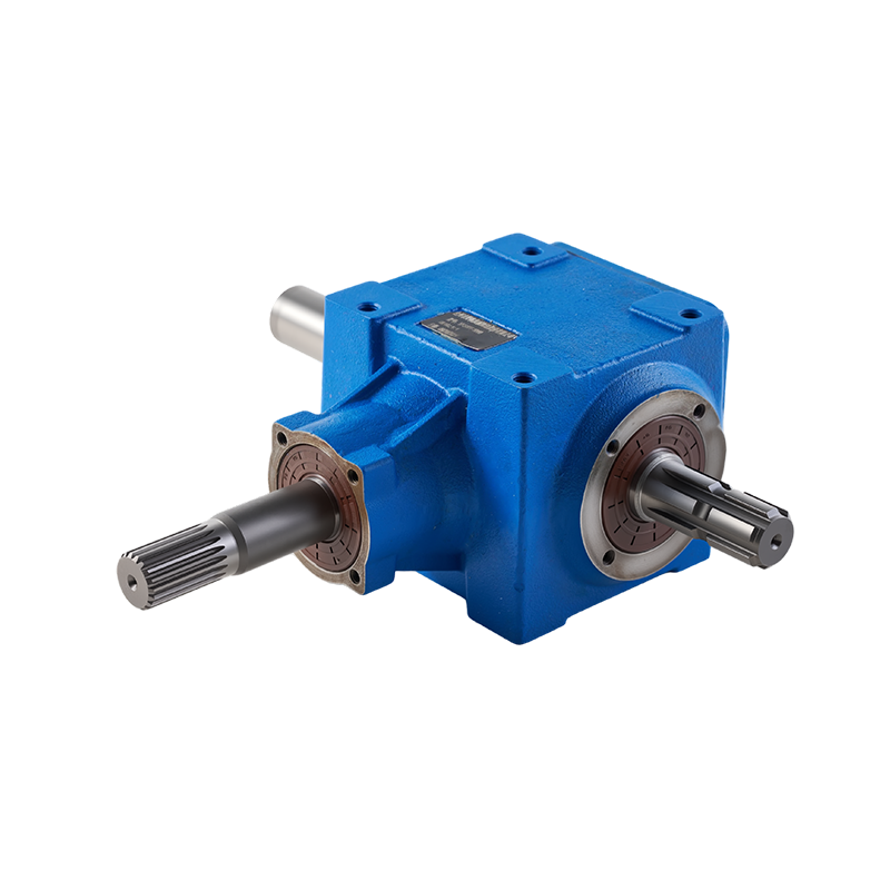
For an Output Gear Shaft, heat treatment also needs to be considered alongside dimensional control because thermal processing can influence the final geometry of a machined component.
Machining Builds The Functional Interfaces
Production can begin with a forged blank or bar stock, depending on the shaft structure and production requirements. Turning operations establish the basic shaft dimensions, followed by processes for gear cutting, splining, keyways, threads, or other detailed features.
The sequence can vary according to the component design. Precision machining is particularly relevant around bearing seats and connection areas because these surfaces directly interact with other transmission components.
Gear tooth finishing may also be used when the application requires more controlled tooth geometry and surface characteristics.
Output Shafts Serve Different Equipment
The same basic component concept can be adapted to many mechanical systems. Automotive transmissions, agricultural machinery, construction equipment, reducers, conveyors, and industrial machinery all use rotating shafts to transfer mechanical power.
An Output Gear Shaft for a compact industrial reducer may have very different dimensions from one used in heavy construction equipment. The required torque, rotational speed, installation space, and connection method all influence the final design.
This is why output shafts are generally developed around specific drawings and transmission assemblies rather than as universal components.
Manufacturing Brings Several Processes Together
The production of an Output Gear Shaft connects material selection, blank preparation, machining, gear cutting, heat treatment, and final inspection. Each stage contributes to the relationship between the shaft and the transmission system around it.
For gear manufacturers, the component is not simply a shaft with teeth added to one section. Its geometry has to support load transfer, bearing locations, gear engagement, and downstream connections within a defined mechanical system.
As power transmission equipment becomes more specialized across vehicles and industrial machinery, the Output Gear Shaft remains an important component for converting controlled gear rotation into usable mechanical output.
-
William Weber:
Phone: +86-13968651722
E-mail: sales01@hsgearworks.com -
Address:
No.9 East Section, Jianan Avenue, Taizhou Bay New District, Taizhou City, Zhejiang Province, China, 318052
Copyright @ Zhejiang Haoshun Machinery Technology Co., Ltd. All Rights Reserved.
Precision Gears Manufacturer
