
 English
 Español
 Deutsch
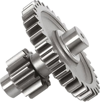
Analysis of Electric Propulsion Gear Reduction Systems
Where Engineering Excellence Meets Reliable Transmission
Let’s Build Your Perfect product.
-
William Weber:
Phone: +86-13968651722
E-mail: sales01@hsgearworks.com -
Address:
No.9 East Section, Jianan Avenue, Taizhou Bay New District, Taizhou City, Zhejiang Province, China, 318052
Copyright @ Zhejiang Haoshun Machinery Technology Co., Ltd. All Rights Reserved.
Precision Gears Manufacturer
